
What Is the Hall Effect and How Do Hall-Effect Sensors Work?
Nearly 150 years after its discovery, the Hall effect remains fundamental to modern magnetic sensing. At its simplest, it explains the phenomenon observed when a magnetic field is applied at a right angle to an electric current moving through a conductor or semiconductor, resulting in a detectable voltage across the material.
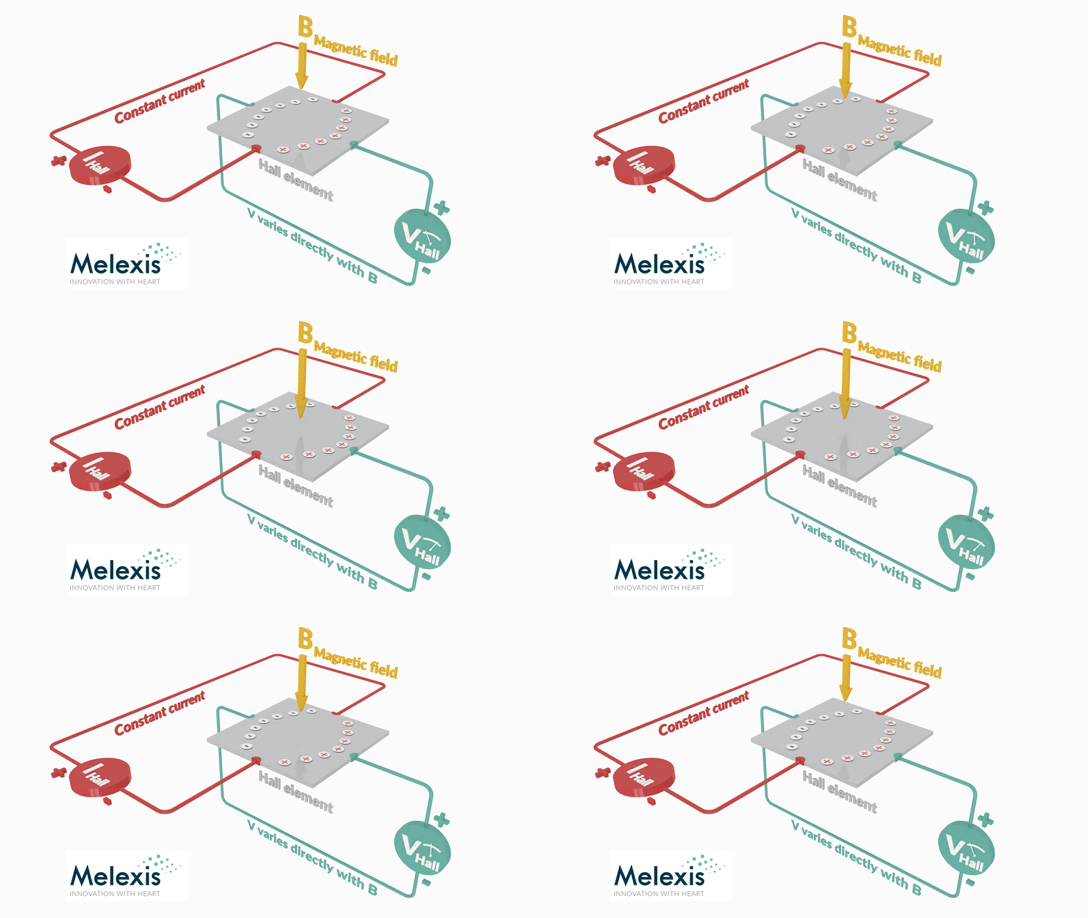
However, that simple physical effect is only the beginning. Turning it into a practical sensor has required advances in everything from materials and semiconductor processes to signal conditioning and magnetic design. Those developments have progressively expanded what Hall-based sensors can detect and where they can be used.
From Edwin Hall’s Discovery to the First Hall Sensors
American physicist Edwin Hall discovered the Hall effect in 1879 while investigating how magnetic fields influence electric current. The discovery was initially used to classify chemical samples, but the development of indium arsenide semiconductor compounds in the 1950s enabled the first practical Hall-effect magnetic instruments. Unlike technologies that depend on a changing magnetic field, Hall-effect sensors could measure DC or static magnetic fields without requiring movement of the sensor.
In the 1960s, the growing use of silicon semiconductors allowed Hall elements to be combined with integrated amplifiers.
One of the continuing challenges was managing offset. This unwanted voltage at the Hall terminals could be mistaken for part of the magnetic signal. Hall transducers progressed from single sensing elements to dual, orthogonally arranged elements designed to reduce this error. Four-element transducers followed, using Hall elements arranged in a bridge configuration to further improve offset cancellation.
Early silicon Hall sensors were manufactured using bipolar semiconductor processes. The move to complementary metal-oxide-semiconductor (CMOS) technology enabled chopper stabilization in the amplifier. By reducing amplifier offset, this technique improved the stability of switching thresholds in digital Hall sensors and reduced offset and gain errors in linear Hall sensors. These developments established the foundations for the more highly integrated Hall sensor integrated circuits (ICs) used today.
How Modern Hall-Effect Sensors Work
The voltage produced directly by a Hall element is small, so a practical Hall-effect sensor needs more than the sensing element alone. Its signal chain typically amplifies and conditions the Hall voltage before converting it into the analog or digital output required by the wider system.
Modern Hall sensor ICs use techniques such as chopper stabilization and active switching of the current through the Hall elements to reduce electrical offset and measurement drift. By taking measurements with the current flowing through the Hall element in different directions, the sensor can distinguish the magnetic-field signal from errors caused by the sensing element, temperature, mechanical stress, and the amplifier circuitry.
Depending on the application, the IC may also incorporate analog-to-digital conversion, temperature compensation, programmable magnetic thresholds, filtering, linearization and signal processing. Outputs can range from a simple on/off signal to an analog voltage, pulse-width modulation (PWM) or a digital communications interface. Integrated diagnostics and dual-die designs also help Hall-effect sensors support functional-safety requirements, such as the Automotive Safety Integrity Level (ASIL) targets defined by ISO 26262 for automotive applications.
The result is a complete sensing system that converts a small physical effect into stable, useful information about a magnetic field.
What Are Hall-Effect Sensors Used For?
Hall-effect sensors convert magnetic flux density into an electrical output. In practice, the field may come from a permanent magnet attached to a moving component or from the magnetic field generated around a current-carrying conductor. Because the coupling is magnetic, the sensor can measure the target without physical contact, reducing mechanical wear and enabling measurement through non-magnetic materials.
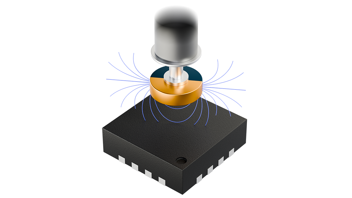
In Hall-effect position sensor ICs, a magnet moves relative to the sensor as the target rotates or changes position. Depending on the sensing architecture, the IC measures the magnitude or direction of one or more magnetic-field components. Integrated signal processing then converts those measurements into information such as rotary angle, linear displacement, joystick coordinates, or actuator position. Applications include vehicle pedals, steering and braking systems, valves, motors, robotic joints, controls, and smart appliances.
Not every application needs to know exactly where something is. Hall-effect latch and switch ICs instead provide discrete state information. Their output changes when the magnetic field reaches a defined operating threshold and switches back at a separate release threshold. The gap between these thresholds creates hysteresis, preventing the output from repeatedly changing when the field is close to the switching point.
Unipolar switches respond to one magnetic pole, while omnipolar switches can respond to either. Hall latches typically change state with one pole and reset when the opposite pole is applied. This makes them useful for detecting whether a door or closure is open, whether a valve or actuator has reached its end position, monitoring fluid levels, and supporting motor commutation. Dual-output latch devices can also derive pulse, speed, and direction information from a rotating magnet.
With Hall-effect current sensor ICs, the current being measured generates the magnetic field. Current flowing through a cable, busbar, or printed circuit board track produces a surrounding magnetic field whose strength changes with the current. The Hall sensor measures this field and uses its calibrated transfer characteristic to produce an electrical output representing the current.
Unlike shunt-based measurement, this approach does not need to calculate current from the voltage drop across a resistor in the primary current path. Depending on the sensor architecture, it can provide galvanic isolation, low insertion loss and non-intrusive measurement. Hall-effect current sensors are used in electric powertrains, battery systems, chargers, power converters, renewable-energy systems and power-distribution equipment.
Hall Effect Versus TMR, GMR, and AMR
Hall-effect sensing is not the only way to convert a magnetic field into an electrical signal. While a Hall element produces a voltage as the field deflects charge carriers in a current-carrying material, a magnetoresistive element responds through a change in electrical resistance. Anisotropic magnetoresistance (AMR), giant magnetoresistance (GMR) and tunnel magnetoresistance (TMR) are the main technologies grouped under the term xMR.
Of these, TMR can provide high sensitivity and fine resolution and, depending on the design, can consume less power than a Hall-effect sensor. These characteristics can be useful when measuring weak magnetic fields or developing battery-powered devices. However, they do not by themselves determine the accuracy or suitability of the complete sensing system.
In a modern Hall sensor IC, the Hall plate can be integrated with amplification and signal processing, alongside functions that compensate for offset and temperature, support calibration and diagnostics, and provide the required output. The finished system's performance also depends on factors such as the magnet, sensor position, package, and mechanical tolerances. Comparing only the sensing elements, therefore, provides an incomplete picture.
Hall-effect sensing is also not confined to one magnetic axis or one type of measurement. A conventional planar Hall element primarily measures the magnetic-field component perpendicular to its surface, but additional structures can enable lateral field components and multiple axes to be measured. The Hall effect can also measure the magnetic field generated around a current-carrying conductor. This versatility has extended Hall-effect technology from basic field detection into more advanced position and current sensing, including the Triaxis® position-sensing and IMC-Hall® current-sensing technologies developed by Melexis.
From Conventional Hall Sensing to Triaxis® and IMC-Hall®
Melexis has extended the flexibility of Hall sensing through its Integrated Magnetic Concentrator (IMC) technology. An IMC is a ferromagnetic structure integrated onto the surface of the sensor IC. It bends and concentrates magnetic-field components that run parallel to the IC surface, allowing the Hall elements beneath it to measure fields that a conventional planar Hall element could not detect directly.
In current sensing, IMC-Hall® technology allows the sensor IC to be positioned over or close to a busbar or printed circuit board track. The IMC concentrates the magnetic field generated by the current into the Hall elements. This can eliminate the need for the large ferromagnetic core used in conventional Hall current-sensing arrangements, although a smaller magnetic shield may still be used to improve sensitivity and reject interference from neighboring conductors.
The IMC is also fundamental to Melexis Triaxis® Hall technology. A conventional Hall plate can measure the magnetic-field component perpendicular to the IC, known as Bz. Melexis Triaxis® technology enables a sensor to measure the in-plane Bx and By components. Combining these measurements allows a single IC to capture magnetic-field information across all three spatial axes.
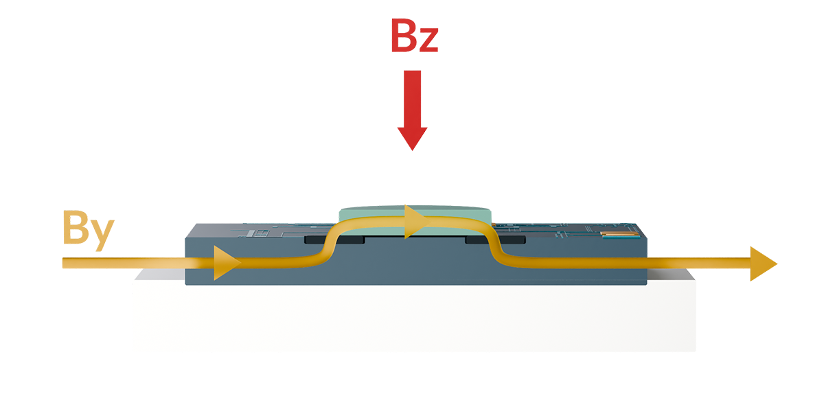
Measuring three magnetic-field components does not automatically mean that every Triaxis® device reports a three-dimensional position. Depending on the product and its signal processing, the measurements can be used to calculate rotary angle, linear displacement, joystick position, speed or direction, or they can be provided directly as raw Bx, By and Bz magnetic-field data.
This flexibility allows engineers to position the sensor beside, below or at the end of a moving magnet, depending on the application. It can simplify magnet selection and mechanical design, provide greater tolerance to sensor placement, and enable measurement in spaces where conventional end-of-shaft sensing is not practical.
Triaxis® Hall technology supports applications ranging from low-power 3D magnetometers and lateral-sensing switches to high-speed magnetic encoders, compact motor-position sensors, and precision robotic-joint sensing. Selected devices can also support stray-field immunity (SFI), high-temperature operation, programmable processing, integrated diagnostics, and functional-safety support.
Hall sensing has therefore developed far beyond the original Hall element. By combining the underlying physical effect with integrated magnetic structures, signal conditioning, and digital processing, modern Hall sensor ICs can address increasingly complex measurement and integration requirements.
Related tech talks


Frequently Asked Questions About the Hall Effect
Yes. A conventional planar Hall element primarily measures the magnetic-field component perpendicular to its surface, while a vertical Hall element measures the magnetic-field component parallel to its surface. Additional sensing structures, including integrated magnetic concentrators (IMC), can also make conventional planar Hall elements responsive to lateral field components. By measuring multiple magnetic-field components, a Hall-effect sensor IC can support two-dimensional and three-dimensional position sensing. Melexis applies this approach within its Triaxis® technology.
A Hall-effect sensor needs a magnetic field, but that field doesn't always come from a permanent magnet. Position, speed, and presence sensing commonly use a magnet attached to the target. In current sensing, the magnetic field is generated by the current flowing through a conductor, allowing the Hall-effect sensor to determine the current without a permanent magnet.
A Hall-effect sensor contains a Hall element through which an electric current flows. When a magnetic field acts on the element, it produces a Hall voltage. Supporting circuitry amplifies, compensates, and processes this voltage to provide an analog, digital, or switching output.
Hall-effect sensors measure position, angle, speed, direction, proximity, magnetic-field strength, and electric current. Common applications include motors, actuators, vehicle controls, battery and charging systems, industrial equipment, robotics, smart appliances, and magnetic switches.
Hall-effect sensors offer contactless operation and can detect magnetic fields whether they are static or changing. In position sensing, this removes the need for contact between the sensor and the moving target, reducing wear and allowing the sensor IC to sit behind a protective plastic barrier.
When electrically biased, a Hall element can respond to the magnetic field from a stationary permanent magnet or from steady direct current (DC) flowing through a conductor. It can also detect changing fields produced by movement or alternating current (AC), within the sensor’s bandwidth. Unlike electromagnetic induction, Hall-effect sensing does not require the magnetic flux to change. Its compatibility with complementary metal-oxide-semiconductor (CMOS) processes also allows the small raw Hall voltage to be converted into a usable analog or digital output within the same IC.
A Hall-effect sensor produces a voltage in response to a magnetic field, while an xMR sensor detects a magnetic-field-induced change in electrical resistance. xMR includes AMR, GMR and TMR technologies. Each approach offers different characteristics, and the best choice depends on the full application rather than a single universal performance advantage.
The Hall effect is the generation of a voltage across a conductor or semiconductor when a current flows through it in the presence of a perpendicular magnetic field. The resulting Hall voltage appears at right angles to both the current and the magnetic field.

The Hall effect was discovered by American physicist Edwin Hall in 1879. His experiments showed that a magnetic field could deflect moving electrical charge carriers and create a measurable voltage across a current-carrying material.


