适用于电机、电子制动助力器和电子助力转向的电感式位置解码器
Melexis 电感式位置解码器芯片具有灵活度高、可扩展的优势,是电子机器转子位置感应的最理想解决方案。
随着汽车电气化时代的来临,对纯电动汽车的需求正在快速增长。无论现在还是未来,每一辆电动汽车都需要一个经济实惠的高性能电牵引电机(电子机器)。而每一台电子机器又需要精确、通用且经济实惠的转子位置传感器。
同步电机需要使用这种传感器信号来驱动电机转矩控制(图 1)。这些信号同步中的错误将会降低系统的整体性能,并可能导致安全问题。
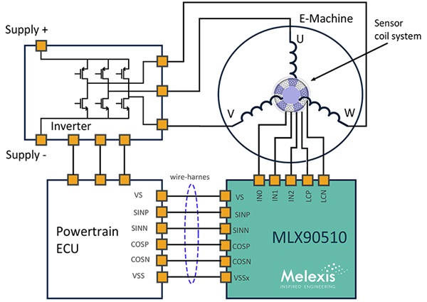
Figure 1: e-motor system view.
转子位置传感器类型
高速转子位置传感器通常有三种类型:可变磁阻 (VR) 解码器、磁性解码器或电感式解码器(图 2)。
可变磁阻 (VR) 解码器
VR 解码器是目前牵引电机中最常用的位置传感器。它由一个铁磁转子和一个带有几个线圈的定子组成。VR 解码器长期应用于电机位置传感应用,并且由于其卓越的鲁棒性,在恶劣的环境中具有优势。
磁性解码器
磁性解码器采用霍尔效应传感器,综合成本优势非常突出。它不仅具有 VR 解码器的特性,而且尺寸紧凑。
电感式解码器
电感式解码器具有精度高、宽速度区间和杂散场抗干扰能力,汽车安全完整性等级可达 ASIL D 。与此同时,与 VR 解码器技术相比,它还降低了电气传动系统的总成本。
| 参数/技术 | VR | 电感式 | 霍尔效应 |
| 精度 | 高 | 高 | 中 |
| RPM (每分钟转速) | 高 | 高 | 中 |
| 杂散场抗干扰能力 (ISO 11452-8) | 有 | 有 | 有限 |
| 系统成本 | 高 | 中 | 中 |
| 输出 | 模拟 | 模拟/数字 | 模拟/数字 |
| 接口 | 额外的 IC | 集成式 | 集成式 |
| 尺寸 | 中 | 中 | 小 |
| 重量 | 高 | 中 | 低的 |
| ASIL (ISO 26262) | 不支持 | ASIL C (D) | ASIL B |
图 2:高速解码器技术比较。
电感式解码器的工作原理是什么?
电感式解码器测量放置在一组感应线圈前的金属靶板的位置。图 3 展示了一种典型的配置。
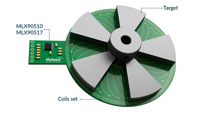
图 3:电感式解码器板示例
一个金属靶板安装在电机转子上。它由若干个与电机的极对数目相匹配的靶瓣组成。线圈组由传输 (Tx) 线圈和接收 (Rx) 线圈组成,固定在电机定子上,通常直接布置在 PCB 中。线圈依次连接到集成电路接口上(图 4)。
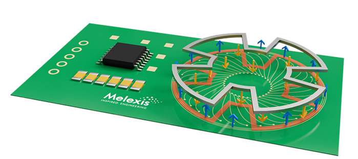
图 4:电感式传感器的基本原理。
在实际应用中,电感式传感器的工作原理如下:
-
Tx 线圈由传感器 IC 控制,激发后可以产生交流磁场
-
靶板与电机的转子一起旋转,根据其位置将磁场反射到线圈上
-
Rx 线圈接收靶板反射的场,并生成一组三个交流信号(3三相线圈设计)
-
位置传感器接口芯片将来自 Rx 线圈的输入信号转化为差分正弦/余弦(基带)输出信号。这些信号用来与电子控制单元通信。ECU 必须执行的唯一计算是通过反正切运算从正弦/余弦信号计算角度。
如需更深入的技术介绍,请详细查看我们的白皮书。
设计一个电感式解码器的模块
在设计使用电感式解码器模块时,必须考虑四个主要方面。即,线圈系统、靶板、芯片(信号处理)和 PCB(图 5)。
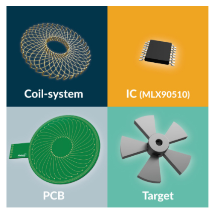
图 5:电感式解码器的四个主要设计区域。
线圈系统
线圈是系统的换能器,等同于磁性系统的霍尔板。当涉及到线圈的设计时,电感式传感器提供了一定程度的设计灵活性。
在线圈设计和设计可扩展性方面,由于传感器(线圈组)没有集成在芯片中,因此可以根据应用的需求进行定制。传感器周期可以根据电机的极对数进行调整。
图 6 所示为一些可变周期的线圈设计。可变周期允许传感器范围与电机的电周期相匹配,从而最大限度地提高传感器的精度。理论上,电感式传感器不存在最大极对数限制。限制主要源于空间和 PCB 设计规则的约束。
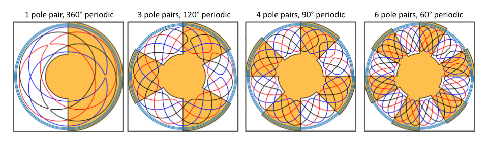
图 6:具有不同周期的电感式传感器示例。
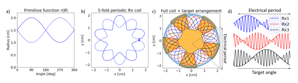
图 7:5 极对、4 cm 直径电感式传感器的线圈设计流程。a) 原函数。b) 个别 Rx 线圈模式。c) 完整线圈组和靶板。d) 一个电周期的 Rx 电压。
图 7 简要说明了如何获得线圈组。Rx 线圈由正弦原始函数 (𝜃)=𝑅0+Δ𝑅sin(𝜃)及其互补函数𝑟′(𝜃)=𝑅0−Δ𝑅sin(𝜃) 定义(图 7a)。然后通过极坐标变换获得 Rx 线圈模式,从而拟合完整一圈内的 N 个周期,N 是电机的极对数(图 7b):
然后,通过添加另外两个平移 120°/N 的 Rx 线圈,一个围绕 Rx 线圈的圆形 Tx 线圈和一个靶板,这样便可得到完整的线圈组(图 7c)。这种配置将提供一个 3 相信号组,如图 7d 所示。
靶板
靶板放置在转子元件上,可根据电机的极对数进行调节。来自Tx 线圈的能量会在靶板中产生涡流,进而产生一个磁场,发送回 Rx 线圈并由其接收。
涡流是根据法拉第感应定律,导体内磁场的变化在导体内产生的电流回路。在垂直于磁场的平面上,涡流在导体内的闭合回路中流动(图 8)。
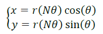
图 8:靶板内的涡流可以看作是单电流,也可以分解成独立的电流回路。
电感式解码器和磁性解码器实际上有相似之处(图 9)。例如,一个三波瓣靶板对应一个六极磁铁。
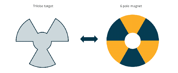
图 9: 一个三波瓣电感式靶板可视为一个六极磁铁。
与电感式靶板相连的接收线圈与磁系统的霍尔板类似(图 10)。
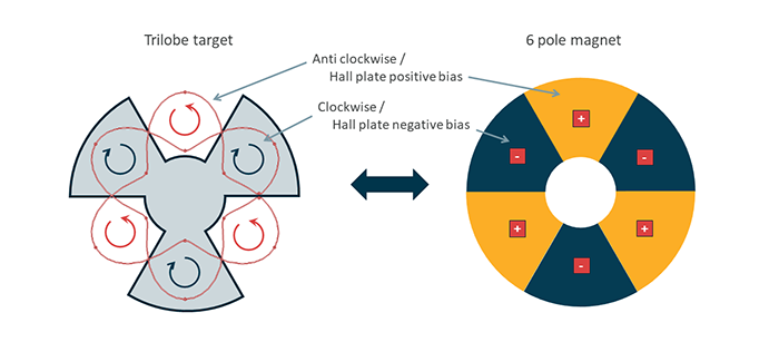
图 10:电感式解码器的 Rx 顺时针/逆时针对应于磁性解码器的霍尔板正/负偏置。
IC(信号处理)
使用电感式解码器,信号处理会直接集成在模块内部(图 11)。Rx 信号由集成接口芯片进行处理,并以正弦/余弦的形式提供给 ECU。信号处理包括共模去除、偏移补偿、数字角度计算、线性化和传播延迟补偿。
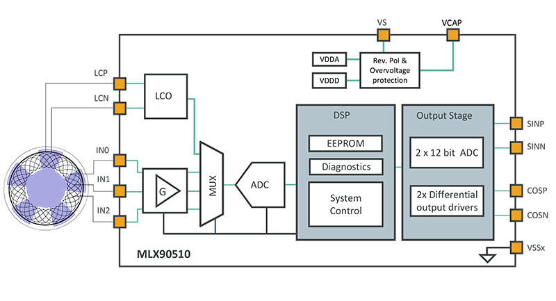
图 11:模拟调节和数字信号处理 (DSP) 由 IC 完成。
PCB
线圈设计既不需要特殊 PCB 设计工具,也不需要特殊的 PCB 技术。
优秀的转子位置传感器应该具有哪些特点?
为了确保准确可靠的运行,转子位置传感器应具备以下特点:
-
在速度大于 200,000 e-rpm(电转速,rpm: revolutions per minute)的情况下提供精确可靠的位置感应。
-
高度精确的位置感应,确保最大效率、最佳转矩控制和低转矩变化。
-
杂散场抗干扰能力。
-
可扩展的灵活设计,适合不同的电机设计和传感器位置。
-
重量轻、经济实惠。
-
汽车安全完整性等级高达 ASIL D。
MLX90510和MLX90517 电感式解码器
Melexis的MLX90510 (MLX90517) 电感式解码器是一款电感式位置传感器 芯片,适用于安全要求严格的汽车应用中的绝对旋转运动/位置感应。它的主要规格为电子机器类型的应用带来的具体益处:
3 相线圈设计
Melexis 采用 3 相(三相)线圈设计,而对于磁系统则可以更直观地采用正交相位线圈设计(图 12)。
三相方法对我们熟悉的误差源(偏移、失配、正交……)没有额外的抗干扰能力。但是,它有一个优点,因为感应信号不像霍尔信号那样是正弦信号。3 相方法通过自动过滤掉一些非理想情况(例如去除偶谐波),简化了线性优化。如需深入了解有关 3 相线圈设计的信息,包括完整理论和验证,请阅读我们的白皮书。
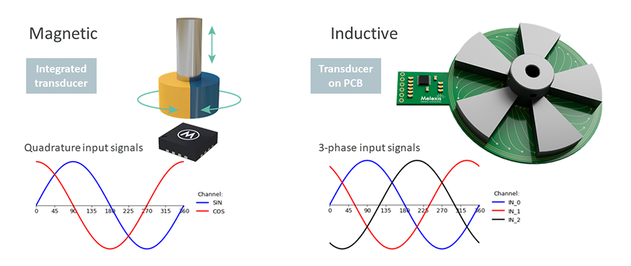
图 12:磁正交输入信号与电感式三相输入信号。
高精确度
MLX90510和MLX90517 采用了创新的数字基础架构,可实现高精确度和高汽车安全完整性等级。
-
在整个工作范围内,系统传播延迟为 <+/- 120 ns。(MLX90510)
-
在整个工作范围内,高精确度 < +/- 0.36° el 高达 240,000 电子 rpm。
机械安装位置灵活性
线圈系统可以印刷在 PCB 上,可以很容易的适应不同类型的电子机器。此外,它还可以灵活固定在轴上(图 13):
-
轴端:小尺寸、低成本、出色的机械稳定性
-
轴通?(通轴):中等尺寸、中等成本、出色的机械稳定性
-
轴侧:大直径小尺寸、低成本、对机械容差敏感
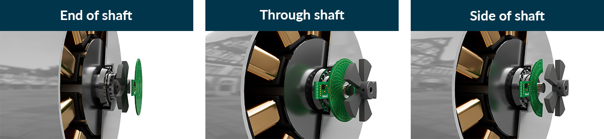
图 13:线圈系统的三个轴固定位置。
改善成本结构
这种电感式位置传感器在一个窄带高频内工作,远远超出了大功率逆变器的开关频率。这就意味着无需昂贵的屏蔽装置。
提高线性度
使用 3 相线圈组而不是典型的正弦/余弦对可以过滤 Rx 信号中一些不需要的谐波,从而提高线性度。此外,MLX90510 提供 16 点线性化,可以减轻机械公差和其他来源的残余误差。
安全
MLX90510和MLX90517 IC 符合 ISO 26262 ASIL C (D) 标准,支持系统集成达到 ASIL D 等级。
耐用(鲁棒性)
-
差分正弦和余弦的模拟输出与由气隙变化引起模拟输入电压幅度变化无关。
-
输入与输出之间彼此去耦,可实现前所未有的 EMC 性能,同时保证稳定输出幅值(不受气隙相关输入信号强度的影响)。
-
工作电源电压范围广,具备过压和反极性保护:-24 V 至 +24 V
-
对直流和交流杂散磁场具有抗干扰能力 (ISO 11452-8)。
-
满足 AEC-Q100 车规要求
-
工作环境温度范围:-40°C 至 160°C。
应用领域
MLX90510和MLX90517 适合多种电动汽车应用(图 14)。
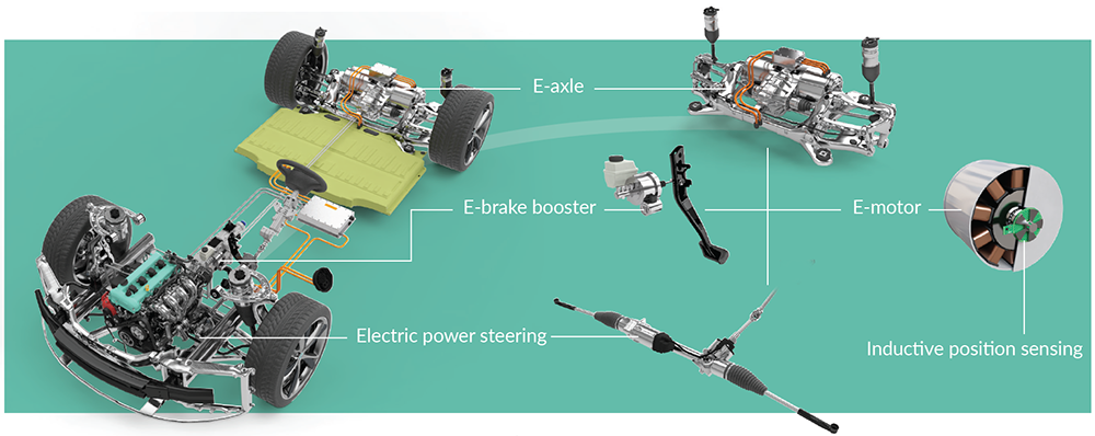
图 14:除电机外,应用方向还包括动力转向,电动制动助力器和电轴。


