智能和互联始于锁存器和开关芯片
与机械开关器件相比,锁存器开关芯片在众多应用中发挥着更关键的作用。锁存器开关芯片增加了灵活性、可靠性、功能安全性、可重复性、准确性和最终组装的产量。本文将介绍它们的工作原理,不同产品类型以及Melexis提供的锁存器开关芯片产品组合。
什么是锁存器和开关芯片?
磁性锁存器和开关芯片基于霍尔效应原理,将磁铁的磁场强度信息转换为数字信号(1 或 0)。因此,其输出为 On(开)或 Off(关),具体取决于所施加的磁场。通过磁铁的位置,锁存器和开关芯片可以确定物体的实际位置。
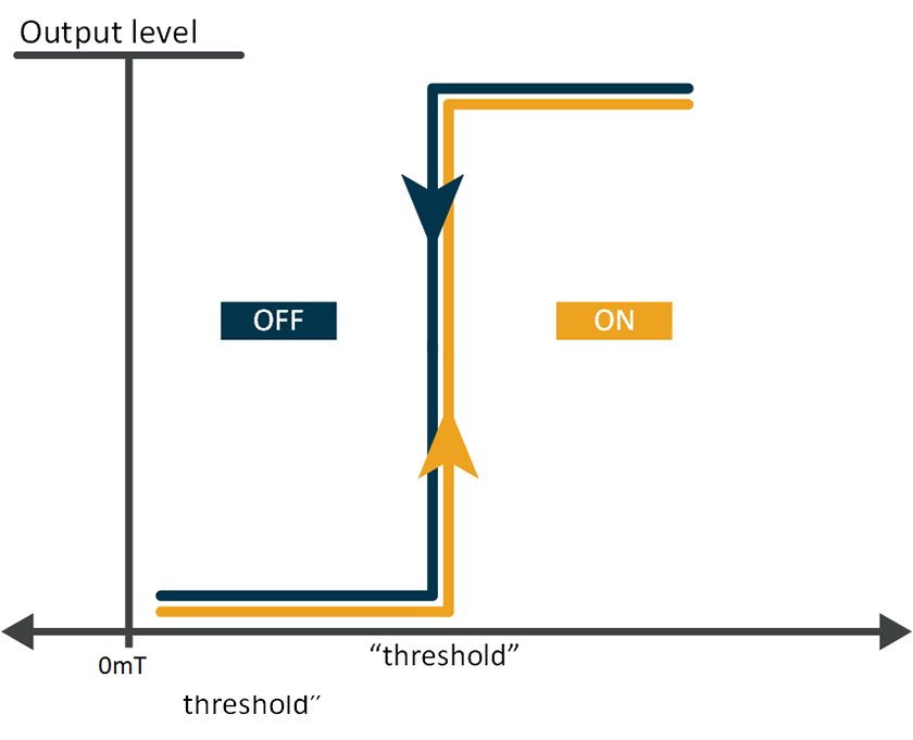
开关原理:
输出在达到定义的阈值时发生变化。
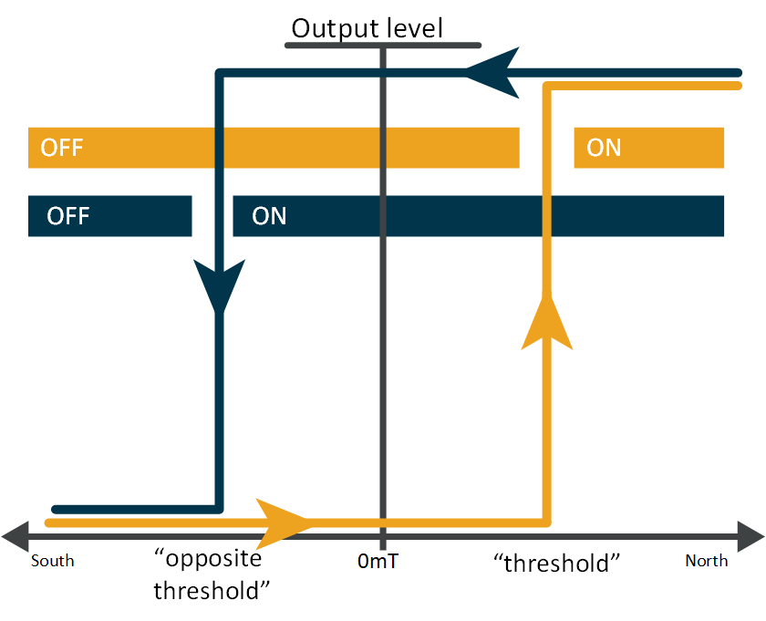
锁存器原理:
这是基于两个相反的阈值进行动作的咖甘。输出首先在达到定义的一个阈值(例如北极磁场值)时发生变化,然后在达到相反的阈值(例如南极磁场值)时再次发生变化。在这两个阈值之间,输出处于锁定状态(保持不变)。
锁存器和开关芯片主要有哪些类型?
锁存器和开关芯片分为三大类。对于这三类,关键参数都是两个开关阈值:BOP,磁场工作点;BRP,磁场释放点。
第一类是单极开关芯片。此类芯片只在一个磁场范围中激活,可以是北极磁场或南极磁场。如果施加的磁场强度高于 BOP 阈值,开关芯片将启用输出。移除磁铁后,磁场强度将低于 BOP 阈值,开关芯片将禁用输出。这种开关芯片主要用于位置检测。
第二类是双极开关芯片,也称为锁存器。锁存器可以在一个磁场范围内激活,在施加相反的磁场时停用。在这种情况下,BOP 定义输出驱动器何时激活(On(开)),而 BRP 定义输出驱动器何时停用(Off(关))。锁存器通常用于 PLC 控制的无刷直流电机换向或直流电机索引计数。
第三类是全极开关芯片,功能与双极开关芯片相同,但可以同时在两个磁场范围内工作。换言之,这类开关芯片在南北极磁场中都能激活,用于检测两个磁场范围的变化。

锁存器和开关芯片应用在哪些领域?
锁存器和开关芯片无处不在,可应用于各种设备,简化我们的生活。这些“开-关”切换器件广泛应用在汽车的制动系统、变速箱、车门锁以及安全带等组件。在电动自行车中,这些器件用于踏板辅助系统、速度计和电机换向,而在电动摩托车中,这些器件还用于触发控制器。
在居家环境中,锁存器和开关器件广泛应用于各种智能家电。这些器件用于确保洗衣机的门已关闭;显示咖啡机的水位和水流量;检测打印机纸张负载以及机盖是打开还是关闭;并且可用于各种电动工具(电机换向、位置检测器等)。
其他应用包括智能楼宇(HVAC 电机换向)、机器人技术(开/关检测、无刷直流电机换向、终点位置检测等)、能源管理(门开/关检测等)和数字健康(健康管理设备电机换向、温度计防水开关等)等。

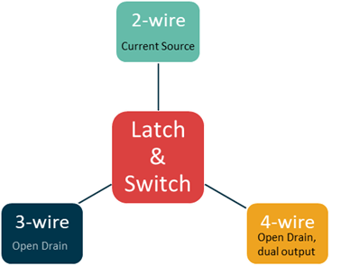
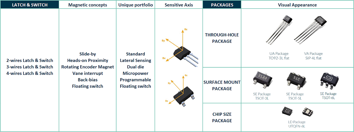
选择正确的输出功能
为选择适合特定应用的锁存器和开关芯片,首先需要选择正确的输出功能。这取决于具体模块以及用于连接另一个系统的电线数量。标准配置为 2 线制、3 线制或 4 线制。这意味着您可以选择输出由电源电流表示的 2 线制传感器芯片;具有开漏输出的 3 线制传感器芯片;以及输出速度(或脉冲)和方向两个信号的 4 线制传感器芯片。
在某些消费类应用中,还可以选择推挽输出类型,而不采用开漏输出。在这种情况下,无需额外使用外部元件(上拉电阻),从而进一步简化模块装配。
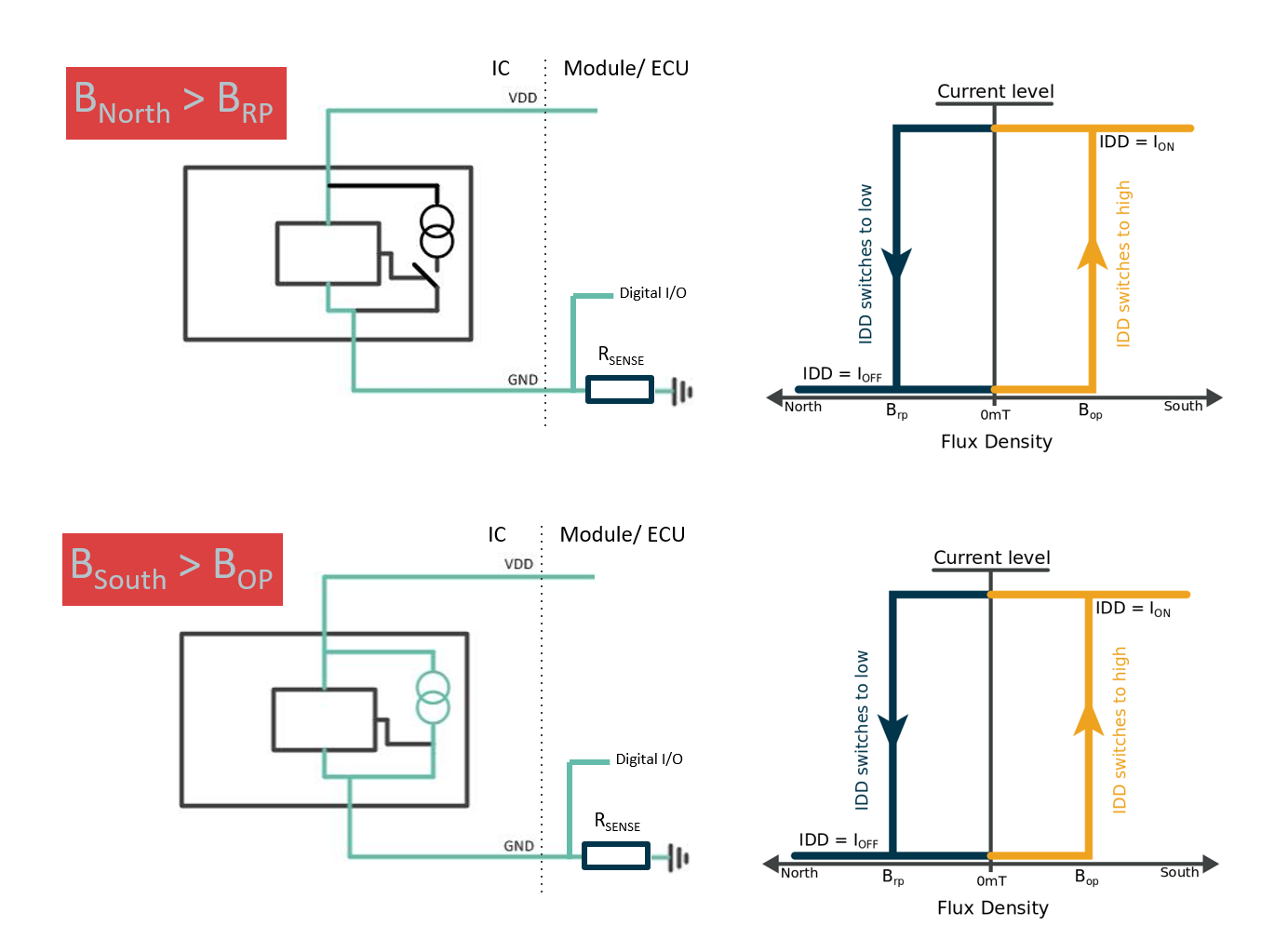
2 线制
这类芯片通常用于远程传感器应用。其主要优势在于,可以替换 2 线制机械开关,同时仍然使用相同的线束。芯片的电流用于识别传感器芯片是否已达到工作点或释放点。
根据行业标准:
- IDD_LO 是指当磁场强度等于或低于 BRP 时产生的电流。有两个值可能适用:通常为 3.3 mA 或 6 mA,具体取决于所选的传感器芯片。
- IDD_HI 是指磁场强度达到 BOP 阈值时部件消耗的电流。该值通常为 14 mA。
电流水平在整个 VDD 范围内保持不变,即使出现一些波动,也能确保读数稳定。检测电阻 RSENSE 所在的回路可将电流输出转换为电子控制单元的逻辑输入。
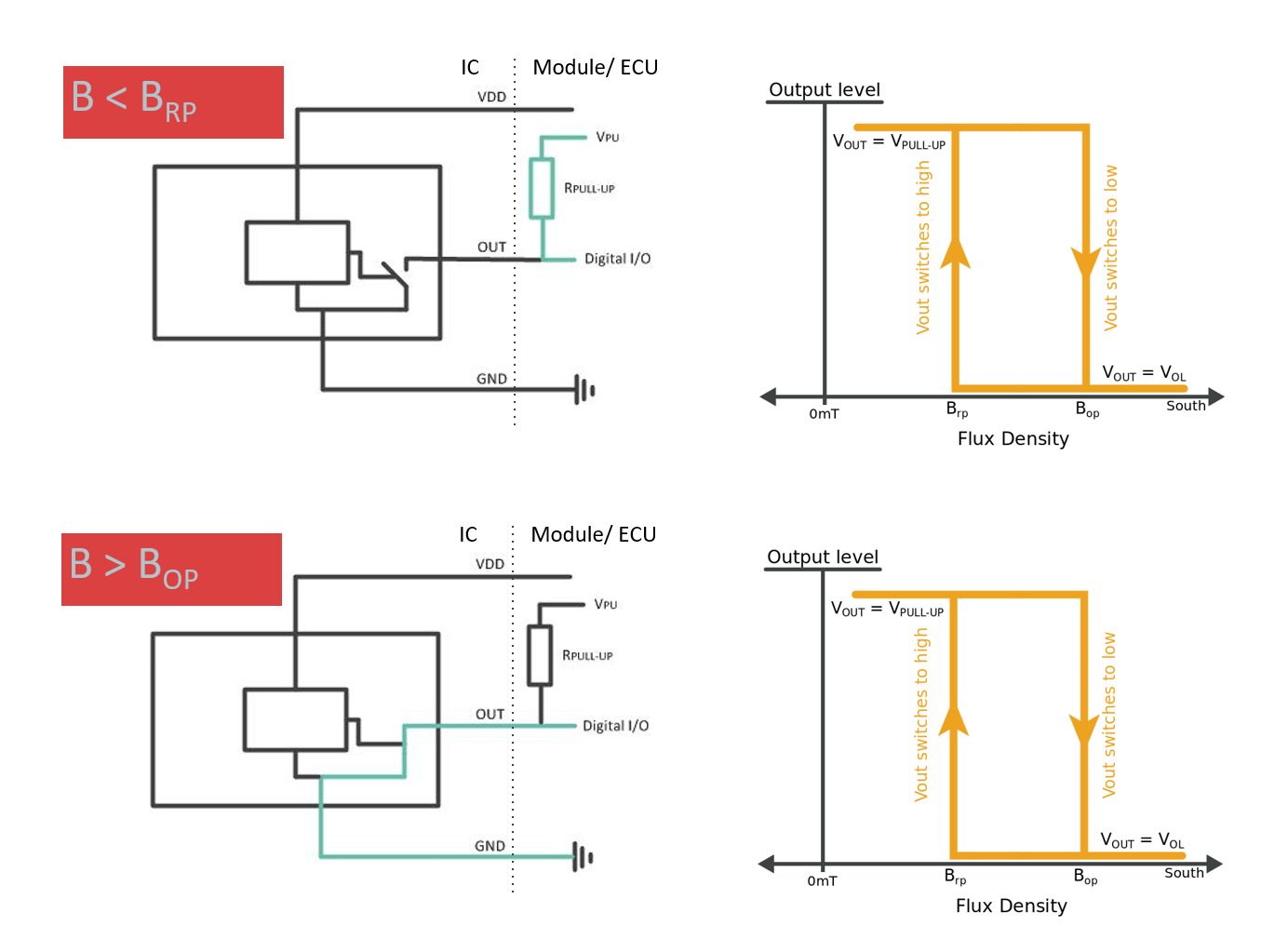
3 线制
这类芯片配有开漏输出。为形成 3 线制,阻性负载必须连接到 VDD 线。典型负载介于 10 kΩ 和 100 kΩ 之间。该负载可以连接在模块侧或电子控制单元侧。达到 BOP 阈值时,输出将接近 0 V。在这种情况下,输出将被禁用并通过上拉电阻连接到 VDD。
4 线制
这类芯片输出两个信号:速度(或脉冲)和方向。速度是锁存传感器的正常输出,而方向输出表示旋转方向是顺时针还是逆时针。这类芯片配有两个霍尔元件,通过使用 CMOS 工艺确保板间宽度固定。
根据锁存磁特性,速度 (SP) 输出会在面向封装顶部的南极或北极磁场强度足够强时分别变为低电平或高电平。磁场去除后,器件会保持之前的状态。
当两个霍尔板上存在特定的磁脉冲序列时,方向 (DIR) 输出会根据所施加磁场的运动方向锁存为低电平或高电平。
Melexis 锁存器和开关芯片有哪些独特特性?
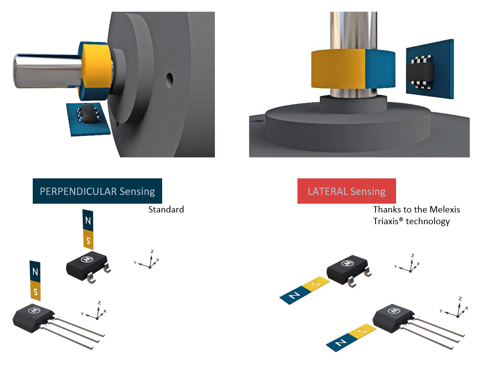
侧向感应选项
侧向感应仅需一个开关即可实现速度检测,适用于摩托车轮速传感器等背向偏置应用。侧向感应还可实现通常需要传统通孔组件的表面贴装器件 (SMD) 解决方案。与其他解决方案相比,回流焊可为其带来更多优势。典型应用包括鼓风机、冷却风扇和泵等。
此外,侧向感应还能提高磁性设计的灵活性,从而实现尺寸更为小巧的电机设计,不受间距影响。典型应用包括汽车行业的车窗升降器和天窗等。
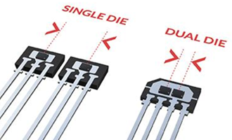
双芯片选项
双芯片选项可提供另一个可编程/预设输出,即芯片共包含两个独立的输出,芯片功能更为丰富,可实现反向输出、报警检测和失磁检测等应用。此外,还能实现更为小巧的 PCB 设计。典型应用包括变速箱、电子锁存器和车窗升降器等。
微功率选项
传感器芯片具有“微功率”的特点,兼具低压运行和低电流消耗优势,特别适合电池供电设备。该器件采用在内部进行管理的休眠/唤醒策略,功耗得到显著降低。典型应用包括保险箱的门锁等。
可编程选项
锁存器和开关芯片可由客户编程,满足客户的各种需求。BRP 和 BOP 可以根据具体应用进行调整。芯片可直接编程,具有很高的灵活性和准确性。
TC 选项
由于不同类型的磁铁(铁氧体磁铁、钕磁铁等)在同一温度下的表现不同,热补偿 (TC) 是某些应用的一个关键参数。因此,选择具有适当 TC 或可编程 TC 的芯片非常重要。
浮动开关选项
浮动开关芯片采用隔离式输出(SOI 技术),只需通电即可直接驱动负载。典型应用包括液位计应用、按钮和负载直接驱动等。此外,浮动开关芯片也可直接替代机械簧片开关。
满足汽车安全完整性等级 (ASIL) 要求的选项
符合 ASIL 要求的芯片依据 ISO 26262 标准设计。此类芯片适用于汽车安全应用,如安全带扣等。
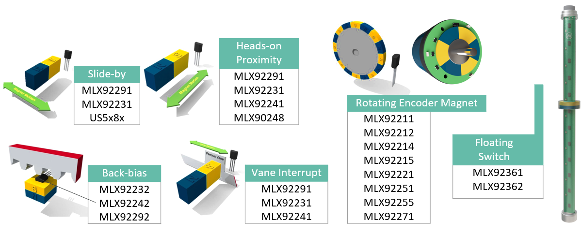
适用于不同应用的不同磁性芯片
Melexis 的锁存器和开关芯片支持多种应用。主要产品描述如下。在选择传感器芯片时,仔细考虑可应用于设计的磁性芯片,为应用选择最合适的产品,实现最佳效果。
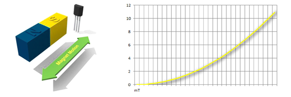
滑动
滑动开关芯片只在一个磁场范围内工作。在下方示例中,已选择南极磁场。当磁铁位于芯片正前方时,磁场强度达到最大值。磁铁只要在平行于芯片的方向上移动,就会减弱磁信号。在此配置中,建议使用单极传感器芯片。
滑动
正面接近
接近开关芯片同样只在一个磁场范围内工作。在下方示例中,磁铁尽可能靠近芯片时,磁场强度达到最大值。磁铁只要朝芯片方向移动,就会增强磁信号。对于这种配置,应使用单极开关。
正面接近应用
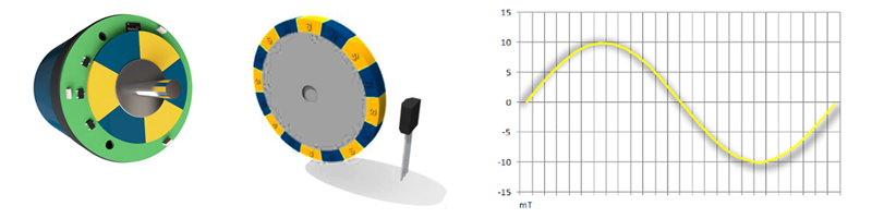
旋转编码器磁铁
圆盘形磁铁通常用于索引计数应用。传感器芯片将通过南极磁场启用并通过北极磁场禁用。对于每个磁极对,传感器信号将切换两次。对于这些配置,非常适合选择锁存器芯片,因为这类芯片在相反的磁场下工作和释放。在请求方向信息的情况下,方向传感器可能是一项优势。
旋转编码器磁铁应用
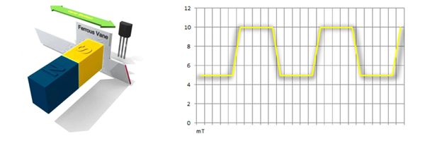
叶片中断
亚铁叶片可用于中断磁信号。该叶片会使磁场强度发生变化并触发传感器芯片的输出。可能仍会对传感器芯片施加一个较弱的磁场。对于这类应用,首选单极传感器芯片。
叶片中断应用
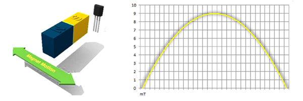
背向偏置应用
对于此配置,可以采用多种实现方案。第一种方案可以使用成本较高的零高斯磁铁来实现,在传感器感应点所在的位置形成一个实际的零磁场区域。这种方案支持使用预编程芯片。
第二种方案可以使用可感应侧向磁场分量的传统磁铁来实现。该方案已借助 Melexis 的 IMC 技术实现。采用这种方案时,可以使用普通磁铁;当侧向磁场分量接近于零时,磁铁在整个温度范围内的表现仍然很稳定。对于这种配置,建议在将芯片安装到磁铁上后进行简单的编程,以确保平稳运行。
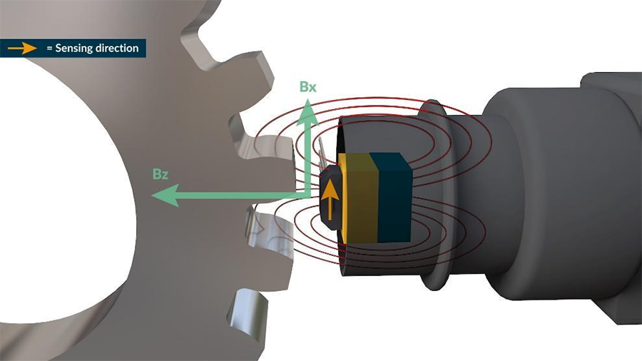
下图表示普通磁铁配置的磁性分量 Bx 和 Bz。Bz(绿线)显示应用中出现大幅偏移(100 mT),说明温度变化会产生很大影响,在整个温度范围内实现良好运行极具挑战性。对于这类应用,通常使用动态补偿传感器芯片,但会导致物料清单成本较高。
磁场的侧向分量 (Bx) 在 0 mT 左右对称,因此具有出色的温度特性,可提高设计的稳定性。采用这种方案(经过 0 mT),可以使用静态开关传感器芯片来控制所需的占空比。芯片安装后可进行编程,这对于提高精度非常关键。对于此配置,建议使用较小的磁滞 +/- 1 mT。
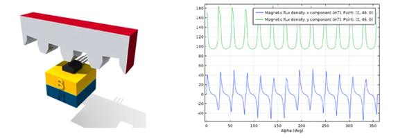
Back bias applications
浮动开关
若搭配一排浮动开关,磁铁可用于检测液位。此外,浮动开关芯片也可直接替代机械簧片开关。
Melexis 锁存器和开关芯片产品组合
Melexis 提供各类锁存器和开关芯片,为多种应用提供支持:
磁性芯片概览
应用
![]()
Melexis 的先进技术和创新产品广泛应用于各种领域。在本概览页面,单击特定应用,然后单击“锁存器和开关”(Latch & Switch) 图标,即可显示应用中所用的芯片。
支持
- Melexis 团队将全力支持您进行创新。
- Melexis 提供可编程以及在出厂时已经编程的解决方案。
- 同时,提供全面的编程工具,为产品开发和生产提供支持。
- 其他支持与指导,请访问芯片处理和组装页面。
如需更多信息,请访问专门的产品页面。
结论
锁存器和开关芯片的应用越来越广泛,这类芯片可用于各行各业的各类应用,实现位置、距离、速度或定向运动检测。此外,锁存器和开关芯片维护成本低,设计坚固耐用,可实现非接触式无磨损操作,并且可免受水、灰尘和振动的影响。Melexis 致力于设计、开发和制造高质量的锁存器和开关芯片。如需详细了解我们的产品组合及其为特定应用带来的优势,请立即联系我们。


