
Temperature Measurement in High-Voltage Equipment
By Kolio Karastoianov, Application & Design Engineer at Melexis
Abstract — Accurate, fast and reliable over time, temperature measurement is a critical parameter across industrial automation, consumer electronics, automotive engineering and medical devices. Selecting the optimal sensing technology depends on operational constraints, environmental factors, and cost considerations. Accurate, reliable temperature monitoring is a cornerstone of high-voltage (>400V bus) power-system reliability. Over-temperature can trigger insulation failure, reduce life time, and cause catastrophic failures due to thermal runaway. This white paper provides an in-depth technical analysis of two temperature sensing technologies that dominate the market: Negative Temperature Coefficient (NTC) thermistors (contact based) and far-infrared (FIR) sensors (non-contact). By evaluating their operational principles, performance metrics, and application suitability, this document offers strategic insights for engineers and system architects. Both technologies can be deployed safely in HV environments, but they differ markedly in insulation requirements and reaction speed. This paper reviews the underlying physics, practical implementation issues, and provides a side-by-side comparison to aid system designers in selecting the most appropriate solution.
1. NTC (Negative Temperature Coefficient) thermistors
The fundamental characteristic of an NTC thermistor is that its electrical resistance decreases non-linearly as its core temperature increases due to the properties of the semiconducting materials used. Because the resistance-temperature relationship is non-linear (exponential), one must use a model to linearize the data:
- Steinhart-Hart Equation: This is the gold standard for accuracy. It uses three coefficients (A, B and C), also known as Steinhart-Hart coefficients, specific to the thermistor model and usually provided by the manufacturer:
\begin{equation} \frac{1}{T} = A + B \times \ln(R) + C \times \left(\ln(R)\right)^3 \end{equation}Where: T is the absolute temperature in Kelvin [K], R is the resistance of the thermistor in Ohm [Ω] - Beta (β) Parameter Equation: A simpler, two-point approximation. It is less accurate over wide ranges but sufficient for many applications:
\begin{equation} R_T = R_0 e^{\beta\left(\frac{1}{T} - \frac{1}{T_0}\right)} \end{equation}Where: RT is the resistance at temperature T (in Kelvin);
R0 is the resistance at reference temperature (usually 25 °C);
β is the material-specific constant. - Look-up Tables (LUT): Often used in low-power microcontrollers to save processing cycles, though they require more memory.
1.1. Circuit topologies
- Voltage Divider: The most common method. The NTC is paired with a fixed precision resistor (RFIXED). The ADC measures the midpoint voltage. For maximum sensitivity, RFIXED should match the NTC resistance at the center of your target temperature range:
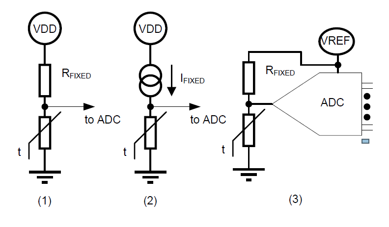
Figure 1: Circuit topologies - Constant Current Source: Used in high-end industrial applications to eliminate lead wire resistance errors, though it is more complex to implement;
- Ratiometric Configuration: By using the same reference voltage (VREF) for both the ADC and the divider circuit, any fluctuations in the power supply cancel out, significantly improving stability.
1.2. Critical design challenges
- Thermal Contact: One must keep in mind that the NTC measures its own temperature. It is thus crucial that there is a good thermal contact between the NTC and the object one wants to measure the temperature of;
- Self-Heating: This is the most common error source. The current used to measure the resistance generates heat (P = I2 × R), causing the sensor to report a higher temperature than the ambient. White papers suggest keeping the power dissipation below 100 µW (better <20 µW) to maintain sub-degree accuracy by using a higher value pull-up resistor or pulse the measurement (turn it on only for a few milliseconds);
- Tolerance Accumulation: One must account for the tolerance of the NTC (often 1% or 5%) and the tolerance of the pull-up resistor. Using a 0.1% precision resistor is standard practice to minimize this;
- ADC Resolution: A 10-bit ADC might be insufficient for wide ranges; 12-bit or higher is recommended to capture small temperature changes at the ends of the curve where the slope flattens.
- Moisture and Aging: NTCs are sensitive to humidity. If moisture penetrates the coating, the resistance drops, causing the system to "think" the temperature is higher than it is.
- Lead Wire Resistance: For remote sensors, the resistance of the copper wires adds to the NTC resistance. This is most critical in low-resistance NTCs (e.g., 1kΩ), even a few ohms of wire resistance can cause a few degrees of error;
- Beta (β) Value Variation: Manufacturers often provide a β value (e.g., 3950). However, β itself changes slightly depending on the temperature range leading to curve-fit errors. An option is to use the Steinhart-Hart equation with three coefficients for high accuracy;
- EMI and Switching Noise: In inverters (EV, BESS, Solar, Windmill), the high-frequency switching (PWM) of SiC/IGBTs creates massive electromagnetic interference. The high resistance (10 kΩ to 100 kΩ typ) and long NTC leads act as antennas, injecting noise into the ADC. This causes "jittery" readings or false over-temp triggers. A fix is to use shielded cables, twisted pairs, and strong low-pass filtering (RC filter) at the ADC input.
1.3. Addressing thermal lag (response time)
High-voltage NTCs often have thicker ceramic or plastic encapsulation for insulation, which increases thermal resistance. The thermal time constant τ is dominated by:
- Sensor mass (0.5 – 2 mg for surface-mount NTCs). Higher thermal mass leads to slower reaction time;
- Thermal coupling to the measured point (thermal interface material, mounting pressure). Worse thermal coupling increases measurement error.
Typical τ ≈ 1 – 10 s, even higher. Faster response can be achieved by:
- Using thin-film NTCs (≤ 0.5 mm thickness);
- Ensure good thermal contact to the measured surface (thermal paste, metal clamps);
- Avoid excessive encapsulation thickness; use high-thermal-conductivity potting (e.g., alumina-filled epoxy);
- NTCs with low thermal mass exist, but these are in general small and very fragile, making them unsuitable for applications with vibrations and shocks.
- Software Compensation: White papers suggest using a Lead-Lag Filter or a Thermal Model in the MCU firmware. By knowing the physical properties of the NTC housing, the software can "predict" the actual junction temperature faster than the physical sensor can react. This increases error and noise however.
1.4. Addressing HV insulation (NTC)
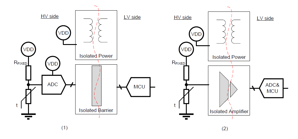
Figure 2: Isolation concepts
1.4.1. Isolated data acquisition (the digital approach)
The most robust modern approach involves placing the entire analog front-end on the high voltage side and sending digital data across an isolation barrier. Schematic Flow: NTC Divider → ADC → Digital Isolator → MCU.
1.4.2. Isolated amplifier (the analog approach)
For systems where the MCU needs an analog voltage directly, isolated amplifiers are used. Schematic Flow: NTC Divider → Isolated Amplifier → Differential-to-Single-Ended Op-Amp → MCU ADC.
2. FIR (far-infrared) sensors
Every object with a temperature above absolute zero emits electromagnetic radiation. Devices like thermopiles convert thermal radiation into electrical signals, while microbolometers utilize changes in resistance. The underlying physics is governed by the Stefan-Boltzmann Law, which relates the power radiated to the temperature of the object:
Where:
E is the total energy, radiated per unit area;
σ is the Stefan-Boltzmann constant;
ε is emissivity of the surface emitting the radiation. The emissivity is a characteristic that indicates how well an object (sometimes referred as a "grey body") radiates heat compared to a perfect source (known as a "black body"), which has an ε=1.
The accuracy heavily relies on the emissivity of the target material. Most plastic or painted materials exhibit ε in the range (0.85 to 0.95). However, metals (aluminum, copper) have very low ε and mostly reflect ambient infrared, leading to highly inaccurate readings unless painted or coated, or explicitly calibrated.
FIR sensors focus the infrared energy (typically in the 5 µm to 14 µm wavelength range) onto a detector element, such as a thermopile or microbolometer. All signal processing is typically accommodated in one package and temperature is sent via a I2C bus (see MLX90637, MLX90614, etc.).
2.1. Addressing HV insulation (FIR)
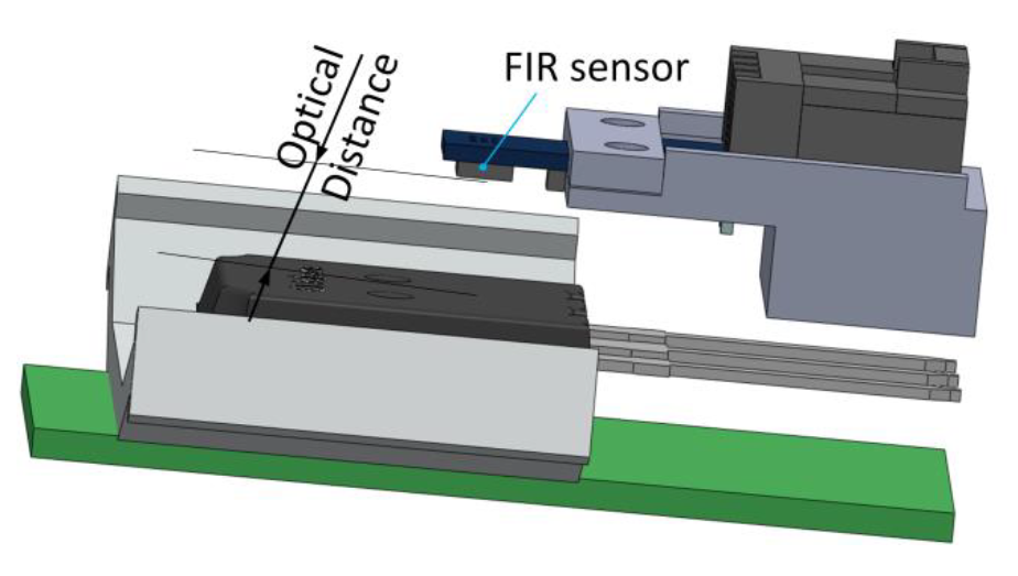
Figure 3: Measuring with FIR sensor
FIR thermometers are non-contact, typically placed at a distance from the measured object, so an intrinsic insulation is obtained naturally via the optical distance. Some devices are housed in a TO-can, sealed and tied to ground, which provides an excellent protection for the electronics. The distance from the object introduces, however environmental susceptibility - dust, smoke, humidity, or physical obstructions in the optical path between the sensor and the target will attenuate the signal and skew the measurement.
2.2. Addressing response time
Depending on the detector type, the modern FIR thermometers provide 1 ms to 100 ms response time supported by often >60 Hz sampling, enabling real-time temperature tracking.
3. Drivers for total cost of ownership
3.1. Unit component cost
NTC Thermistor: They are incredibly cheap. However, in HV applications, you often need a glass-encapsulated or epoxy-coated version with reinforced insulation, which can push the price up.
FIR Sensor (SMD): High-grade automotive FIR sensors are significantly more expensive per unit.
3.2. "Hidden" system costs (the real difference)
To use an NTC safely in an 800 V (and above) inverter, you must add components that FIR sensors don't require:
| Cost Element | NTC System (HV) | FIR System (HV) |
|---|---|---|
| Isolation IC | Requires an isolated ADC or amplifier ($2.00 - $4.00). | None (senses through air gap). |
| Isolated Power | Needs an isolated DC-DC converter ($1.50 - $3.00). | None (uses standard LV rail). |
| TIM (thermal interface material) | Requires thermal paste or conductive pads to ensure accurate contact with the heat source. | None (FIR is non-contact). |
| High Emissive Paint/Coat | None. | Needed when measuring bare metals. |
| Assembly Labor | High: often requires manual gluing, clipping, or wiring. | Low: fully automated SMD pick-and-place. |
| Consolidate Multiple Sensors | A separate sensor is needed for every heat source or battery cell. | A single, low-resolution multi-pixel FIR array can monitor all three phase bus bars, as well as the DC link bus. |
| PCB Space | Large (requires 8 mm+ creepage distances). | Small (often a standard SMD footprint). |
| Standard Single-Board Design | Often requires a separate board with connector and wiring harness. | Allows integration of the temperature sensing function directly on the main control board. |
| Calibration | Required to compensate for thermal lag/offsets. | Required to set emissivity values. |
| Diagnostics | Requires external diagnostics. | Often includes on-chip self-test features. |
4. Design recommendations
4.1. Define the measurement goal
Internal, not time response critical, temperature control → NTC;
Time response critical, hot-spot detection, or moving or inaccessible points → FIR.
4.2. Select insulation strategy early
For NTCs, choose a high-dielectric potting material and a grounded guard ring; verify dielectric strength >10 kV/mm.
For FIR, ensure the optical window material and housing meet the required voltage standoff and temperature rating.
4.3. Control self-heating (NTC)
Limit excitation current to keep power <20 µW; use a high-value series resistor to set the current.
4.4. Emissivity management (FIR)
Calibrate each measurement point with a known-emissivity reference paint.
4.4.1. Coating selection and application
Bare metals (copper, aluminum) have a very low emissivity parameter (ε = 0.1 to 0.2), so their surface needs to be treated (paint, coat, etc.) for FIR temperature measurement.
| Coating Type | Key Features | Max Operating Temp | Emissivity (ε) |
|---|---|---|---|
| Matte Black BBQ/Exhaust Paint | Excellent adhesion, thermal shock resistance, cost-effective. | 600 °C to 1000 °C | ~0.95 |
| Matte Kapton Tape | Non-permanent, good for testing, electrically safe. | 260 °C | 0.94 to 0.96 |
| Black Electrical Tape | Easiest temporary fix, low-temperature use only. | 105 °C | ~0.95 |
| Standard Coating (PET) | Standard process. | 105 °C | 0.91 to 0.95 |
| Standard Coating (PI) | Standard process. | 200 °C | 0.88 to 0.92 |
| Standard Coating (Powder) | Standard process. | 105 °C | 0.94 to 0.95 |
High-heat matte black BBQ or exhaust paints (such as those from VHT, Rust-Oleum Specialty High Heat, or Stove Bright) are typically silicone-ceramic based:
- Temperature range: These paints typically handle 600 °C to 1000 °C, far beyond what a copper busbar should ever reach.
- Thermal shock: Because they are designed for exhaust headers, they handle the rapid heating and cooling cycles of a busbar without cracking or flaking.
4.5. Signal conditioning
Use isolation amplifiers or digital isolators for NTC voltage dividers; for FIR, place the detector electronics in a grounded enclosure or use the all-in-one fully integrated sensors like MLX90614, MLX90637, etc.
4.6. Sampling rate vs. thermal dynamics
Match the sensor’s τ to the expected temperature change rate. For slow-changing transformer or motor windings, a 1 Hz sample from an NTC is sufficient; for Li-Ion battery runaway or arc-flash detection, a high-rate FIR sensor is required.
5. Comparative summary
| Feature | NTC | FIR |
|---|---|---|
| Insulation complexity | Requires potting, guard rings, or isolation amplifiers. | The intrinsic optical isolation is usually sufficient. |
| Response time | Seconds to minutes (depends on thermal mass). | 1 ms to 100 ms (detector τ). |
| Contact | Direct (requires physical mounting). Assure good thermal contact between sensor and object by using thermal paste/pads. Assure lifetime of the paste. |
Non-contact (line-of-sight). |
| Typical accuracy | ±1 °C (after calibration and only valid in steady state). | ±0.5 °C (depends on emissivity). |
| Component cost | Cents. | Dollars. |
| Installation | Requires wiring through HV barriers; careful routing to avoid stray fields. | Simple mounting; only a clear view needed. |
| Choose for | A strict BOM limit, a proven manual assembly process, and voltage below 400 V. | An 800 V (or higher) SiC (silicon carbide) inverter where EMI is high, space is tight, and manual wiring and expensive isolation ICs need to be eliminated. |
6. Conclusion
Both NTC thermistors and far-infrared (FIR) temperature measurement techniques are viable for high-voltage applications, yet they serve complementary roles:
- NTC thermistors excel when a permanent, embedded temperature point is needed. Their low cost, high accuracy (±1 °C), and straightforward electronics make them ideal for monitoring heat-sinks, winding packs, and power-module cases. The primary design challenges involve ensuring reliable thermal contact and electrical insulation, which can impact the system's overall thermal response time.
- FIR thermometry provides a highly accurate (±0.5 °C), non-contact, and fast-response solution for hot-spot detection, inspection of sealed enclosures, and continuous monitoring of live conductors where physical contact is expensive, hazardous or impossible. By managing emissivity through proper calibration or coatings, FIR sensors provide a precision measurement without the insulation complexities or "hidden" costs associated with contact-based sensors.
While NTCs are limited by the thermal mass of their encapsulation, FIR sensors offer millisecond-scale response times, enabling high-precision tracking of rapid thermal events. By applying the insulation techniques and response-time optimizations outlined above, reliable temperature measurement can be achieved even in the most demanding high-voltage environments.

