Position sensors for motor control feedback loop
What’s the use of a position sensor for motor drivers?
This tech talk provides an overview of Melexis magnetic position sensors for motor commutation and/or positioning. Discover magnetic solutions: latch/switch, linear Hall or resolver. To learn about the technical concepts, please refer to the complete application note (chapter 5).
Position sensors for motor driver
Electrical motor drive is a complex domain with many use cases. In this area there are motor drivers that can perfectly operate without a position sensor (sensorless). So why add extra component(s)? Let’s first distinguish the two possible roles that can play a position sensor here.
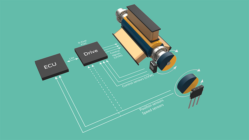
Figure 1: general building blocks and paths to enable motor commutation and application positioning
Motor control can have multiple feedback loops: one for the motor commutation and one for the positioning. These control loops do not necessarily use the same position sensor since different characteristics are needed to optimize the system and BOM. Position sensors can improve the control of the system in the following areas: position, torque or speed.
Position Control
- Enables a known (safe) position at startup and throughout motion
- No missed steps when using stepper motor
Torque Control
- Enables low speed and low noise generation especially for larger motors like pumps
Speed Control
- Enables reliable startup
- Low speed drive
- Capability to handle highly dynamic loads
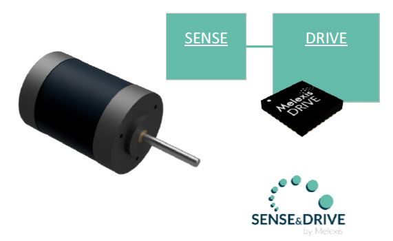
Figure 2: Benefits of a position sensor in motor drive application
Motor commutation
Position sensors can be an integral part of the motor commutation control loops for several types of electrical motors.
The motor control algorithm determines the currents through the coils and the timing of those currents. The angle of applied field has to be in quadrature to the rotor’s field direction for maximum efficiency.
Concepts are fully detailed in the application note (chapter 5), but note that the type of motor control algorithm is linked with the motor design and the sensor type. For example, brushless motors can work with trapezoid control, sinusoidal control and field oriented control:
- Trapezoid control, the basic, can use latch/switch readout for the position of the rotor. It is sufficient for a Brushless DC motor (BLDC). This concept supports high speed but torque ripple might be present and unwanted. Imagine an accelerating electrical car where the acceleration is not smooth.
- Sinusoidal control or Field Oriented Control will behave better however they require an accurate angle position of the rotor (an angle with much higher resolution). The more accurate, the higher the efficiency will be and in some cases even better safety. These control algorithms can also be used for a Permanent Magnet Synchronous Motor (PMSM).

Figure 3: latch and linear principle

Figure 4: resolver principle
Application positioning
Position sensors can be required for the application positioning. Take for example a critical smart valve. The position sensor ensures a correct position of the valve independently from its motor position. Another example is a robot arm where the servo motor accurately positions a joint.
Here, the sensors needed for motor positioning might be the one(s) used for motor commutation. This is especially true if the rotor shaft’s position and the motor’s output shaft are 100% correlated. This is not always the case however. In some cases, an internal gear box converts a high speed/low torque rotor to a lower speed/higher torque output shaft. It then might be necessary to put an additional – lower speed- sensor on the output sensor.
Melexis Products
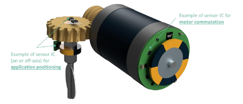
Sensor ICs for motor commutation
This chapter gives a high level overview of 3 different hall based product categories for motor commutation: latch/switch, linear hall and resolver.
| Motor Commutation (High speed) | Low resolution | High resolution |
| Multiple IC | Latch/Switch | Linear Hall |
| Single IC (or dual IC for redundancy) | Resolver |
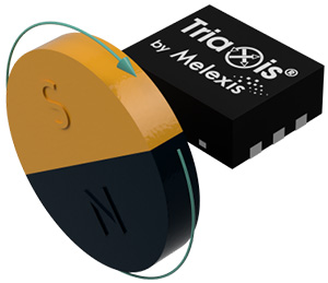
Motor commutation with Latch/Switch
Latch/Switch products are placed in the stator in a multi-IC configuration. They are interesting for trapezoid control of BLDC motors: 3 ICs are used, 1 for each phase.
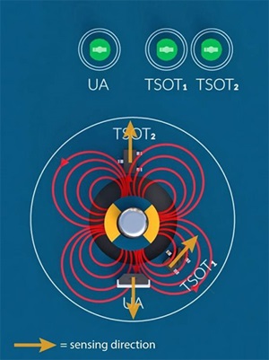
Figure 5:
Lateral or perpendicular sensing
Melexis provides a whole range of Hall Effect latches with fixed, pre-programmed or programmable parameters. Next to the traditional sensors which are sensitive to the magnetic flux density that is applied perpendicular to the die surface, Melexis offers latches that sense a lateral magnetic flux density. This feature brings a large flexibility in the positioning of the sensor versus the magnet (rotor or sensing magnet). The sensors are available in a single die TSOT-3L or TO92-3L. Melexis also offers the first ASIL-B capable latch/switch on the market.
Discover more
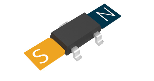
Figure 6:
Lateral / X-axis
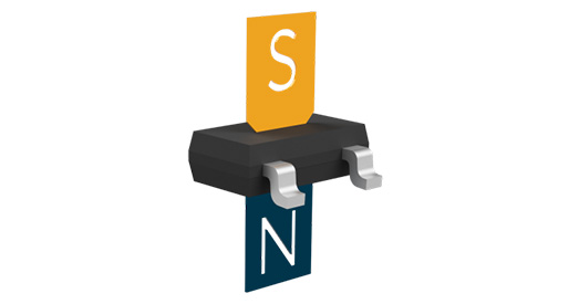
Figure 7:
Perpendicular / Z-axis
Motor commutation with Linear Hall
A linear Hall Effect sensor can be used to replace the hall Latch sensors. Using multiple sensors in quadrature gives the absolute angle of the rotor with high angle resolution. Their analog output makes it possible to calculate, with a dedicated algorithm, a much more accurate rotor position. This makes them not only suitable for detecting the motor commutation point but also for an accurate position control.
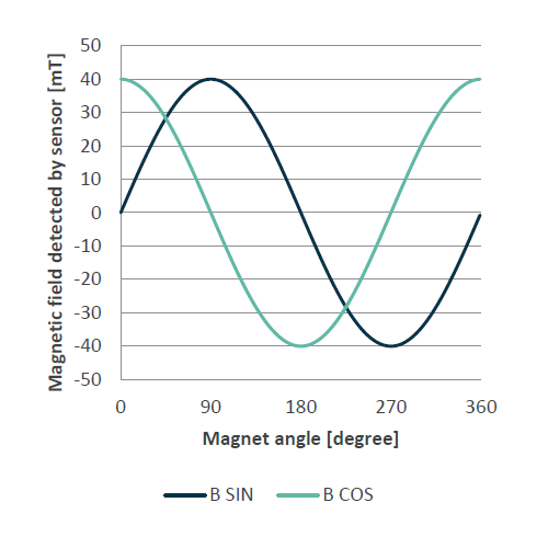
Two linear hall sensors placed at a 90° magnetic phase shift can also be used as a sine cosine angle sensor. The angle α is calculated from the arctangent of SIN over COS.
Discover more
- MLX90290 (High Speed Pre-Programmed Linear Hall IC, analog ratiometric output)
- MLX90296 (Micropower Linear Hall IC, DFN4 package, analog ratiometric output)
- All Melexis Linear Hall ICs
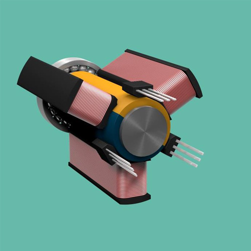
Figure 8: setup with 3 sensors
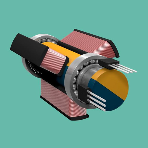
Figure 9: setup with 2 sensors
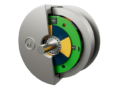
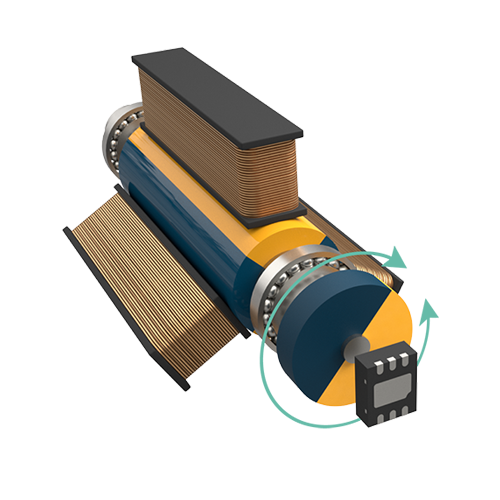
Motor commutation with Magnetic Resolver
Magnetic Resolvers, also known as resolvers or motor resolvers, are fast IC solutions which provide ratiometric analog sine-cosine outputs. These outputs are representative of the rotor magnetic flux and thus can be used to detect the motor position. The latest generation can be placed either on-axis (End of Shaft) or off-axis (Though Shaft).
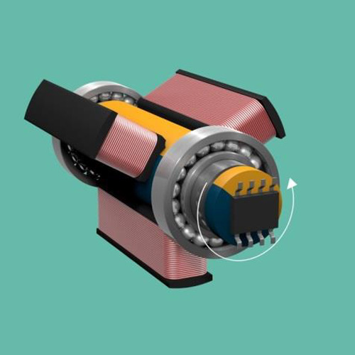
Figure 10: End of Shaft
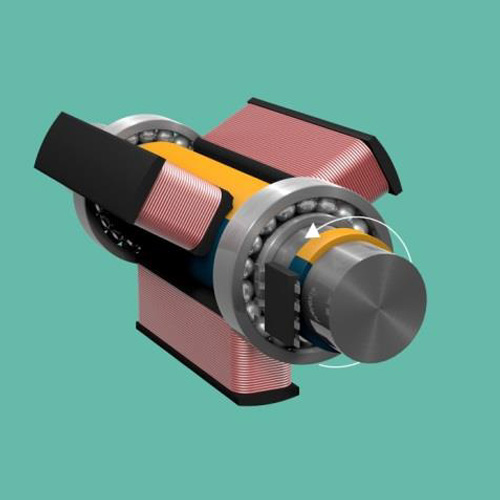
Figure 11: Through Shaft
Triaxis® Resolvers have an X-Y-Z magnetic axis configuration. This feature brings a large flexibility in the positioning of the sensor versus the magnet (rotor or sensing magnet).
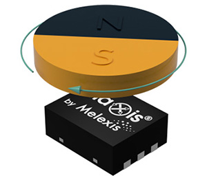
X/Y Magnetic Axis
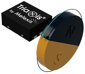
X/Z Magnetic Axis
Y/Z Magnetic Axis
OUT1 and OUT2 (Sine and Cosine signal) of the sensor can be configured in X/Y magnetic axis, X/Z magnetic axis or Z/Y magnetic axis for End Of Shaft or Through Shaft sensing.
Discover more
- MLX90380 (Triaxis® Resolver, 360 Degree, two ratiometric analog outputs, high speed)
- MLX90381 (Triaxis® Pico-Resolver, 360 Degree, two ratiometric analog outputs, high speed)
- Latch & Switch selection tool
Sensor ICs for positioning
Some motor applications have an extra control loop for positioning. Think for example a valve for which the actuator runs at lower speed. Or when the application uses an internal gearbox to convert a high speed/low torque rotation to a low speed/high torque rotation. Due to wear in the gearbox, the 1-1 relation between rotor position and motor output shaft is lost. As such, some designs put an extra position sensor on the output shaft.
| Application Positioning (Lower speed) | Raw information (Embedded) | Computed angle (Standalone) |
| Combined with the motor commutation | Latch/Switch | |
| Resolver | ||
| Linear Hall | ||
| Specific performances | Triaxis Value Optimized (Magnetometer) | Triaxis Mainstream (MLX9042x) |
| High performances | Triaxis Performance (MLX9037x) |
The products mentioned for the motor commutation are very focused on high speed. Their update rate is expressed in few µs, and they generally output raw information. This information is then treated by the related MCU. For the application positioning, the fast response is no longer the main focus. Therefore, we can use “smarter” sensors that output already computed angle information. Such a sensor benefits from a DSP and therefore offers more functionalities (signal compensation, programmable diagnostics…) which can further simplify the system design. Melexis offers a wide range of angular position sensors at lower speeds. Here, low speed means an update rate from 200µs.
Discover more
- MLX90392/MLX90393/MLX90395/MLX90397 (Value optimized, Magnetometers requiring post processing. For consumer or automotive applications)
- MLX9042x (Mainstream, Magnetic Position Sensor for cost conscious but demanding applications)
- MLX9037x (Performance, Magnetic Position Sensor with the highest performance, safety and feature set requirements)
- Selection guide Magnetic position sensors - Triaxis® for Automotive and Industrial
- Selection guide Magnetic position sensors - Triaxis® for E-mobility, Smart appliance, Home, Industrial & Medical
Driver ICs for actuator
Melexis’ all-in-one LIN motor driver and pre-driver reduces BoM and simplifies design of automotive mechatronic applications: motor-controlled flaps, valves, fans and pumps. The devices are also used in robotic systems and e-bikes/e-scooters.
They support 2-wire DC motor, 3-wire BLDC motor or 4-wire bipolar stepper motor, using either sensored or sensorless field-oriented control (FOC) algorithms.
For sensored applications, Melexis is your one-stop-shop with Sense & Drive solutions. Absolute angle position sensors can be used with Melexis' driver ICs, to drive and sense the position of a smart valve for efficient cooling of the battery or engine. It is also compatible with Melexis' pre-driver ICs to track the rotor position in smart pumps, to control the pump efficiently and dynamically with the right torque.
Our complete third generation of embedded drivers includes:
- the LIN drivers MLX81330 and MLX81332 for 1..10 W applications
- the LIN pre-drivers MLX81340, MLX81344 and MLX81346 for 10..2000 W applications
Note that with the MLX81346, Melexis is the first company to bring a fully integrated 48 V pre-driver System-on-Chip (SoC) to the market.
Discover more
- LIN motor driver (current < 1 A)
- LIN motor pre-driver (current > 1 A)
- Selection guide Smart LIN motor drivers
General concepts summary
For the details, please refer to the application note (chapter 5).
Here is a summary of the concept:
| System | Latch/Switch | Linear Hall | Resolver |
 |
 |
 |
|
| Concept | 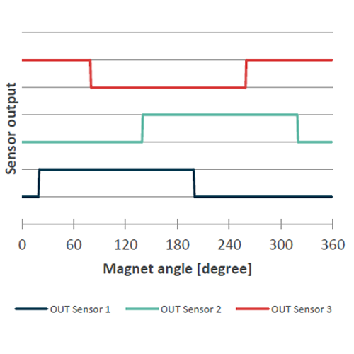 |
 |
 |
| 3 latches for a 3 phase system (placed at 60°) Use the duty cycle (DC) to operate |
2 linear sensors (placed at 90°) Generate Sine and Cosine to operate |
1 resolver Provide Sine and Cosine to operate |
|
| Pros | - Cost | - High resolution - Detect motor commutation point |
- High resolution - Allows absolute position control (e.g. 2 pole magnets is sufficient) - End of shaft position is possible |
| Cons | - Low resolution - Multiple sensors (x3) implying: * precise positioning * part to part variation to compensate |
- Multiple sensors (x2) implying: * precise positioning * part to part variation to compensate |
- Cost |
Conclusion
Motor drivers can be supported by position sensors to meet specific application requirements related to the position, torque and speed control. Melexis Sense & Drive offers the right solutions to optimize your mechatronic applications.


